Steel profiles with plates
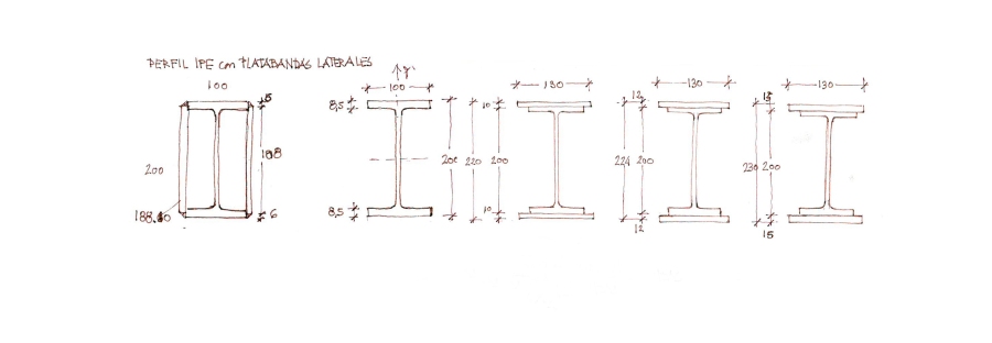
Los perfiles con platabandas son perfiles formados mediante la soldadura de unas platabandas a un perfil laminado para mejorar sus características mecánicas, fundamentalmente su resistencia a flexión o torsión. La limitación a estos añadidos es la compatibilidad entre el espesor de las alas del perfil y el de las platabandas cuando se sueldan.

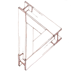
IPE profile and IPE profile with plates forming closed sections.
Las respectivas instrucciones nacionales limitan la dimensión mínima de las gargantas de soldadura en ángulo, a, en función del espesor de la chapa. Para la EAE (Instrucción de Acero Estructural, España), siendo t el espesor del perfil, la garganta mínima es:
- 0 < t ,max < 10 mm; a,min = 3,0 mm
- 10 mm < t ,max < =20 mm; a,min = 4,5 mm
- t, max > 20 mm a,min = 6,0 mm
Igualmente, para la norma de la Sociedad Americana de Soldadura (AWS), la garganta debe ser entre 0,18t y 0,27t.
Y para la norma suiza:
- 0 < t ,max < 17 mm; a,min = 4,0 mm
- 17 mm < t ,max < = 25 mm; a,min = 5,0 mm
- t, max > 25 mm a,min = 6,0 mm
Por otro lado, la garganta de soldadura máxima también está limitada a:
a <= 0,70 t,min
En la práctica, estas limitaciones impiden la soldadura convencional de chapas cuya relación de espesores sea mayor de 2:1.
Tanto en el caso en el que las platabandas se suelden en las alas como en el que forman un cajón, estas aumentan la superficie de la sección del perfil, y en consecuencia, su capacidad para resistir los esfuerzos axiles. Pero dependiendo de la posición de las platabandas, se mejora el comportamiento a flexión o torsión.
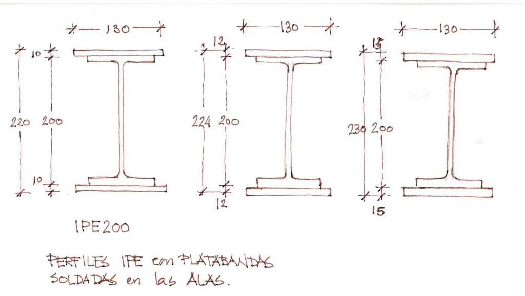
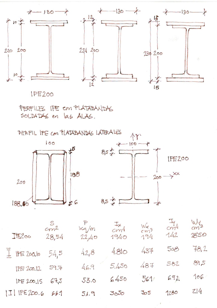
Las platabandas soldadas a las alas de los perfiles de acero aumentan la sección en la posición más alejada del eje de simetría horizontal (eje X). Esta disposición provoca un aumento de la inercia y el módulo resistente respecto al eje principal de inercia, pero reducida respecto al eje secundario (Y). Por el contrario, cuando la soldadura de las platabandas es lateral, el aumento de la inercia respecto al eje principal de inercia es menor, pero el aumento de la inercia respecto al eje secundario es mayor.
Si lo que se pretende es mejorar la resistencia a flexión respecto a un eje y disminuir la deformación por flexión en un único plano, la solución de los perfiles con platabandas superior e inferior es la más eficiente. Ahora bien, si el objetivo es un aumento de la resistencia a flexión en ambos planos de simetría, como puede ser el caso de un pilar, la solución de platabandas laterales es más eficiente. Otra situación en la que esta solución también puede ser más adecuada es en los casos en los que se necesite un buen comportamiento a torsión. Frente a estos esfuerzos, las secciones cerradas trabajan mejor que las secciones abiertas.
Comparison between IPE profile and IPE profiles with welded plates.
The profiles with plates are pieces constructed by welding plates to the laminated profiles. In this way, we improve the mechanical characteristics and, especially, the resistance to bending and torsion. The limit of these additions is the compatibility between the thickness of the wings of the profiles and the plates for welding.
Different national regulations restrict the minimum dimension of the weld throat, a, in a cross section depending on the thickness of the plates. For the Spanish regulation EAE (Regulation for structural steel), when t is thickness of the profile, the minimum weld throat is:
- 0 < t ,max < 10 mm; a,min = 3,0 mm
- 10 mm < t ,max < =20 mm; a,min = 4,5 mm
- t, max > 20 mm a,min = 6,0 mm
Similarly, the Regulations of the American Welding Society (AWS) state that the weld throat should be between 0.18t and 0.27t.
And for the Swiss regulation:
- 0 < t ,max < 17 mm; a,min = 4,0 mm
- 17 mm < t ,max < = 25 mm; a,min = 5,0 mm
- t, max > 25 mm a,min = 6,0 mm
On the other hand, the maximum weld throat is also limited to:
a <= 0,70 t,min
In practice, these restrictions prevent a conventional welding of plates with a thickness ratio of 2:1
The plates welded increases the surface of the section and its resistance to axial. It does not depend on the place of the plates: on the wings or forming a closed section. On the other hand, the position of the plate is important over the increase in resistance to bending and torsion.
The plates welded on the wings increase the surface of the section at the point furthest from the axis of horizontal symmetry (axil X), but smaller on the secondary axis (Y). On the other hand, when the plates forming a closed section, the increase in inertia with respect to the main axis of inertia is smaller, but the increase in the secondary axis is greater.
When we want to increase the resistance to bending on an axis and decrease bending deformation, the welding of plates on the wings is the most efficient solution. But, if we want to increase bending resistance in both symmetry axis, the profiles with plates welded making a closed sections is more efficient. Another situation in which closed sections are more appropriate is when we need a good performance against torsional force. Closed sections are more efficient than open sections against these force.
